
Argomenti trattati
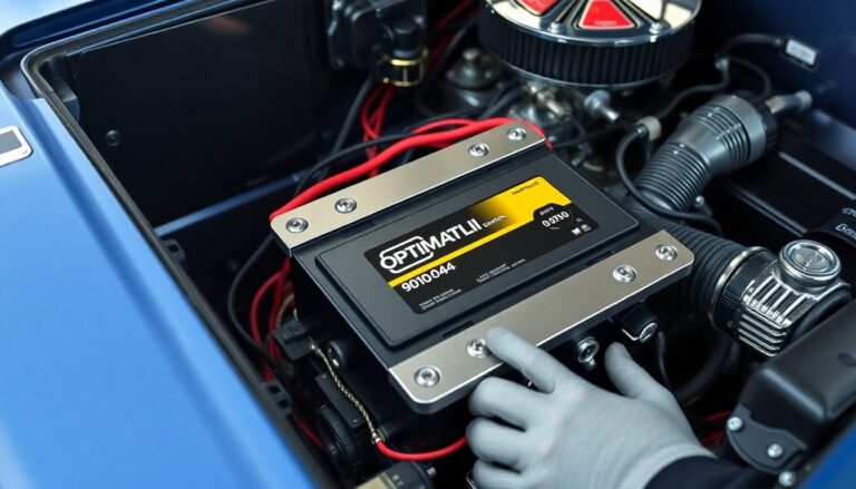
The Granatelli Motor Sports 6-volt OPTIMA battery tray is a purpose-built mounting solution that balances strength, fitment versatility, and visual refinement for custom and restored vehicles. Machined from billet aluminum using CNC processes, the tray is tailored to secure the Optima 9010-044 6-volt battery while presenting a tidy, professional appearance in the engine bay.
This product is supplied as a complete kit so installers have everything required for a tight, reliable mounting. The tray is available in a black anodized finish and is suitable for a variety of projects including classic restorations, performance builds, and show cars where both function and presentation matter.
Design and construction
The data shows a clear trend: builders prefer components that combine mechanical integrity with clean aesthetics. From a strategic perspective, the Granatelli tray addresses both demands.
Manufacturing uses CNC-machined billet aluminum to control tolerances and repeatability. The material choice yields a favourable strength-to-weight ratio and resists corrosion when finished. The kitized supply model reduces on-site fabrication time and simplifies installation for professional shops and experienced enthusiasts.
Key practical features include precision mounting points sized for the Optima 9010-044, integrated hold-down provisions, and countersunk fastener locations to maintain a low profile. The black anodized finish offers surface protection and a subdued visual presence compatible with restored and modified engine bays.
From a strategic perspective, installers will value the reduced fitment guessing and the consistent presentation across multiple builds. The operational framework for adoption is straightforward: verify battery model compatibility, confirm chassis clearance, and follow the supplied torque and sealing guidance.
Materials, finish and physical specifications
Transitioning from fitment considerations, the tray’s construction balances rigidity with corrosion protection. The primary plate and supports are CNC-machined from billet aluminum to preserve dimensional stability under repeated load cycles. The black anodized coating provides corrosion resistance while reducing surface reflectivity inside engine bays.
The unit weight is approximately 5.0 lbs. Shipping dimensions are roughly 12″ x 10″ x 3″. Compact packaging reduces transport damage risk and simplifies storage for restorers and custom shops.
From a strategic perspective, choosing billet over stamped or cast alternatives lowers the risk of fatigue-related deformation. The data shows a clear trend: rigid platforms maintain clamping geometry longer, which helps preserve electrical contact and hold-down security over a vehicle’s service life.
Compatibility and fit
Verify three critical clearances before installation: terminal reach, hold-down engagement, and adjacent component spacing. Confirm battery model compatibility against the tray’s footprint and hold-down locations.
Terminal orientation and post height determine whether the tray suits top-post or side-post battery variants. Check cable routing and post accessibility with the battery seated to avoid later rework. Confirm chassis clearance for thermal and vibration exposure when the vehicle is at full suspension droop.
Thermal coupling and vibration transfer should be considered. The rigid billet platform reduces flex, but close proximity to heat sources may accelerate electrolyte evaporation on some battery chemistries. Ensure adequate ventilation or thermal shielding where necessary.
Installation guidance and practical steps
The operational framework for a robust installation consists of pre-check, fitment, securement, and verification stages.
Concrete actionable steps:
- Pre-check: confirm battery group size and terminal type against the tray footprint.
- Fitment: place the battery and verify terminal access, hold-down alignment, and chassis clearance.
- Securement: install hold-down hardware and tighten to supplier torque specifications provided with the product.
- Routing: arrange positive and negative cables to avoid sharp edges and heat sources; apply protective sleeving where required.
- Vent management: route any vent tubes to an external drain or safe area away from electrical components.
- Electrical test: verify battery voltage and secure terminal connections before closing the engine bay.
- Final check: inspect for metal-to-metal contact with moving parts and confirm no interference at full suspension travel.
From an operational perspective, document the battery model and installation notes for future maintenance. Concrete documentation reduces diagnostic time if electrical issues arise.
Maintenance and longevity considerations
Periodic inspection extends service life. Check for surface oxidation on terminal hardware and reapply anti-corrosion compound as recommended by battery manufacturers. Inspect mounting hardware for loosening after initial road miles and at regular service intervals.
The unit weight is approximately 5.0 lbs. Shipping dimensions are roughly 12″ x 10″ x 3″. Compact packaging reduces transport damage risk and simplifies storage for restorers and custom shops.0
The tray is configured to accept the Optima 9010-044 6-volt battery, offering a secure fit for horizontal or vertical installations. It targets restorers and custom shops that require flexible placement in confined or unconventional engine bays. From a strategic perspective, the design balances universal compatibility with robust mechanical retention to reduce vibration-related failures during road and track use.
Mounting and included hardware
The kit includes a main mounting plate, four spacer mount stands to set tray height, and two top hold-down brackets that clamp the battery. A stainless steel hardware kit is supplied to resist corrosion at contact points. These components simplify installation and maintain long-term durability under varied environmental conditions.
Key features: the spacer stands allow adjustable clearance for heat sources and accessory routing. The top brackets provide positive restraint without deforming the battery case. Stainless fasteners reduce maintenance and prevent galvanic corrosion where mixed metals meet.
Orientation options
The tray supports both horizontal and vertical battery orientations without additional adapters. Vertical mounting reduces footprint where lateral space is limited. Horizontal mounting lowers the centre of gravity where layout permits.
The operational framework consists of selecting the preferred orientation, setting spacer height, and securing the hold-down brackets. The data shows a clear trend: flexible orientation options increase applicability across custom builds and vintage restorations, reducing the need for bespoke fabrication.
Installation notes
During installation, verify tray clearance from heat sources and moving components. Use the spacer stands to set at least the manufacturer-recommended gap from exhaust headers and steering linkages. Tighten stainless fasteners to specified torque values and recheck after initial road use.
Concrete actionable steps:
- Position main plate and mark chassis mounting points.
- Install spacer mount stands to achieve desired height.
- Place battery in tray and attach top hold-down brackets.
- Secure stainless hardware and torque to specification.
- Perform a post-install inspection after first 50–100 km of driving.
Perform a post-install inspection after the first 50–100 km of driving. The tray’s adjustable mounting permits installers to set the battery either horizontally or vertically to match available space and visual objectives.
Choosing the correct orientation reduces the need for custom brackets and preserves factory clearances for steering and suspension components. It also simplifies cable routing by aligning terminals toward existing harness paths. From a strategic perspective, orienting the battery to optimize weight distribution can improve front-to-rear balance on light vehicles and race-oriented builds.
Applications and practical considerations
The tray suits several workshop scenarios. In classic car restorations it enables a tidy, period-appropriate fit while using modern materials for longevity. For custom and performance projects the billet construction offers rigidity under heavy vibration and a refined appearance that matches aftermarket hardware. Show cars benefit from the tray’s clean lines and black anodized finish, which integrates with polished or painted engine-bay components.
Installers should assess three practical constraints before finalizing placement: engine-bay clearance, terminal access for maintenance, and routing for charging or monitoring leads. Verify that vertical installation maintains the battery’s recommended orientation from the manufacturer. Ensure mounting hardware is torqued to specification and that any additional insulation prevents chafing against nearby components.
Concrete actionable steps:
- Mock-fit the tray in both orientations to test clearances and terminal access.
- Dry-route cables to confirm minimum bend radii and secure tie-down points.
- Use vibration-rated fasteners and verify torque after the initial road test.
Document the chosen orientation and routing in the vehicle’s service record to support future maintenance and warranty validation.
Continue the service record entry with the tray’s orientation, cable routing and the packaging information provided at delivery. Record shipment details when relevant for warranty claims and future audits.
When planning installation, account for inbound logistics and carrier restrictions. The product ships and must be transported; domestic promotions may apply, for example free shipping to the lower 48 on qualifying orders. Package dimensions and weight determine box fitment and carrier eligibility. The tray’s SKU is 452200 for the standard billet version and 452200B for the black anodized variant where listed separately.
Practical tips for installers
Verify battery terminal clearance and cable routing before final mounting. Ensure charging and starter cables follow the shortest safe path without sharp bends or contact with suspension or exhaust components. Use insulated clamps where routing passes through metal openings.
Use the spacer mounts to fine-tune ride height and achieve correct alignment with the vehicle’s battery hold-down points. Adjust until the top hold-down brackets compress the battery uniformly without deforming the case. Tighten hardware to the manufacturer’s torque specification in incremental steps and recheck alignment after each pass.
For vehicles exposed to moisture, road salt or coastal environments, rely on the supplied stainless steel hardware to reduce corrosion risk. From a strategic perspective, implement a scheduled inspection cadence: inspect fasteners and terminal connections at first service and every three months thereafter. The data shows a clear trend: regular inspections prevent retention failures and electrical faults caused by loosening or corrosion.
Protect terminals with dielectric grease and secure cables with abrasion-resistant clips. Where space permits, route a short length of heat-resistant sleeving over cables near exhaust and engine hot spots. Confirm the tray remains accessible for maintenance without requiring removal of major assemblies.
Document the final orientation, spacer settings and any routing modifications in the vehicle’s service record. This supports warranty validation and simplifies future troubleshooting. Concrete actionable steps: check clearance, set spacer height, torque fasteners to spec, apply terminal protection, and schedule the first post-install inspection after 50–100 km as previously advised.
Specifications and ordering info
Continue monitoring fastener torque to specification, protect terminals with dielectric grease, and schedule the first post-install inspection after 50–100 km as previously advised.
The tray is machined from billet aluminum and finished in black anodize. It is compatible with the Optima 9010-044 6-volt battery. Standard kit contents: a main plate, four spacer stands, two top-surface hold-down brackets, and a stainless-steel hardware kit.
Typical packaging dimensions are approximately 12″ x 10″ x 3″. Typical shipped weight is about 5.0 lbs. UPC references appear on product listings to support accurate ordering and returns.
From a strategic perspective, verify the UPC and vendor SKU before purchase. Confirm warranty terms and retain shipment documentation for possible claims. Record the seller, order number and shipment date in the service record for traceability.
The data shows a clear trend: buyers prioritize both secure retention and engine-bay presentation. This tray balances precision machining, corrosion-resistant hardware and an aesthetic finish suitable for daily drivers and show cars alike.
Concrete actionable steps:
- Confirm compatibility with the Optima 9010-044 battery model on the vendor page.
- Compare UPC/SKU across listings to avoid counterfeit or mismatched parts.
- Inspect contents against the parts list immediately on receipt.
- Document packaging condition and keep the box for warranty returns.
- Log order number and vendor contact in the vehicle service record.
From an operational viewpoint, ensure mounting surface flatness and clearance for cable routing before final installation. Retain all hardware and packaging for at least the warranty period.
Final technical note: confirm that shipping documentation lists the exact UPC and part number. This detail simplifies warranty support and replacement ordering without ambiguity.